Why a Medical Device Line Chose a Flexible Feeder Over Vibratory Bowl and Centrifugal Feeders
Parts feeding is the quiet bottleneck of automated assembly. A robot can place a component in well under a second, but it can only work as fast as parts are presented to it in the correct orientation, and for many lines the feeding stage is where the reliability actually breaks down. When a medical device manufacturer approached SunAura Machinery to help automate a small-parts assembly cell, the central decision was not which robot to buy. It was how to feed a family of delicate, periodically redesigned components across more than a dozen active SKUs without turning every changeover into a half-day mechanical project. The choice came down to three established technologies: a vibratory bowl feeder, a centrifugal feeder, and a vision-guided flexible feeder. This article uses that project to explain how the three differ and why the customer’s decision was driven by the production profile rather than by raw speed.
The lesson generalizes well beyond medical devices. Any plant juggling multiple part numbers, frequent engineering revisions, or components that scratch, bend, or tangle faces the same trade-off between dedicated mechanical tooling and programmable flexibility.
The Production Problem That Framed the Decision
The customer’s cell had to handle a rotating set of small plastic and metal components, some with fine terminal features and polished surfaces that could not tolerate cosmetic damage. Several parts were symmetrical or nearly so, which makes mechanical orientation difficult, and the product range was expected to evolve as new device generations launched. Batch sizes varied, and the line was expected to switch between part types several times a week rather than run one component for months on end. Two requirements therefore mattered more than headline throughput: changeover had to be fast and repeatable without a specialist technician, and the feeding process had to handle delicate and hard-to-orient parts without scrap or jams.
Option One: The Vibratory Bowl Feeder
The vibratory bowl is the historical default and remains a superb piece of equipment in the setting it was designed for. An electromagnetic drive vibrates a bowl so that parts climb a spiral internal track. Along that track, custom-machined wiper blades, narrowing sections, cutouts, and gravity traps physically reject any part that is not in the desired orientation; correctly oriented components continue to the outfeed while the rest tumble back to the bottom. For a single, rigid, geometrically asymmetric part produced in large volume, a dedicated bowl delivers high feed rates at a relatively modest capital cost and runs for years with little attention.
The same characteristics become limitations in a high-mix cell. The bowl is dedicated to one geometry, so every part type needs its own tooling, and every engineering revision can require re-machining or replacing that tooling. Changeover is a mechanical job — unbolting and swapping bowls, aligning tracks and nests, and tuning gates and blow-offs — commonly measured in hours rather than minutes. Delicate parts also suffer: repeated contact with metal tracks causes surface scratching, fine pins and lead frames can bend against wiper blades, and thin stamped parts can shingle and wedge between track walls, stopping the line. Parts that are oily, sticky, or electrostatically charged can cling to the track and starve the downstream station.
Option Two: The Centrifugal Feeder
The centrifugal or rotary feeder takes a different mechanical route. A motor spins a shallow disc, typically at tens to a few hundred revolutions per minute, and centrifugal force pushes parts outward toward a peripheral track. Orienting tooling around the rim — selectors and rails adapted to the rotating motion — sorts the parts as they pass, and correctly oriented components are guided to the outfeed. Because the action is continuous and smooth rather than a vibrating climb, centrifugal feeders can be quieter and gentler than bowls and are capable of very high feed rates for lightweight, relatively simple parts such as caps, closures, and small symmetrical components.
They are still part-specific, however. The rim tooling is dedicated to a given geometry and must be changed mechanically between part types, so the centrifugal feeder does not solve the high-mix changeover problem even though it improves handling. Parts that tangle, interlock, or are very delicate or complex are poor candidates, and the reliance on centrifugal force means very light or oddly weighted components may not move predictably. In the right high-volume, single-part application it is excellent; in a multi-SKU medical cell it shares the core weakness of the bowl.
Option Three: The Vision-Guided Flexible Feeder
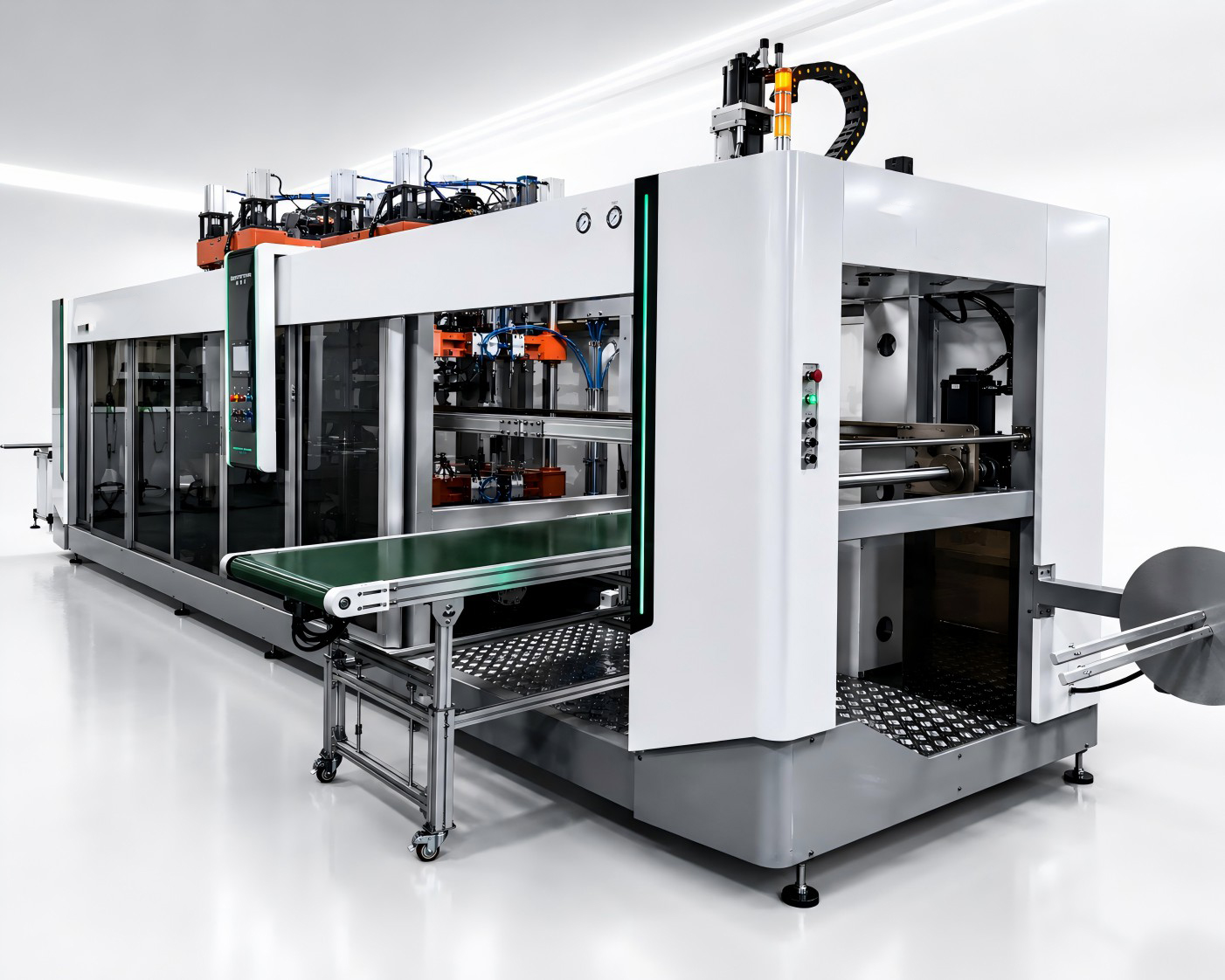
The flexible feeder deliberately separates agitation from orientation. A flat feed deck is driven by multi-axis voice-coil or electrodynamic actuators that vibrate along independent axes to spread clusters and flip parts without forcing them through geometric obstacles. An overhead camera, paired with image-processing software, scans the backlit deck, identifies which parts are in a pickable position and orientation, and sends precise coordinates to a robot — usually a SCARA or a six-axis arm fitted with a suction or mechanical gripper. The robot picks the ready parts while unpicked components remain on the deck for another pulse or return to the bulk hopper. Orientation is decided by software and vision, not by a fixed track, so the same hardware handles many different parts.
The deck surface is typically finished with medical-grade polyoxymethylene, silicone, or an antistatic coating that absorbs impact and prevents cosmetic damage, and because the platform is open and flat with no constricting track, parts cannot physically wedge or jam. Changeover is a software operation: the operator selects a stored recipe, the machine runs a short purge cycle, vibration and vision parameters load for the new part, and production resumes. Integrated systems of this type cover a wide component range, from sub-millimetre pieces up to around 150 millimetres, with placement repeatability on the order of ±0.05 millimetres.
Selection Table: Three Feeding Technologies Compared
| Dimension | Vibratory bowl | Centrifugal | Flexible (vision-guided) |
|---|---|---|---|
| Typical feed rate | High for one part | Very high, smooth continuous feed | Moderate; roughly up to 45 parts/min per single robot |
| Relative price | Lower | Mid | Highest (vision + robot + actuators) |
| Changeover difficulty | Mechanical swap, hours | Mechanical rim tooling, hours | Software recipe, minutes |
| Part variety | One geometry per bowl | One geometry per set of tooling | Many parts on one system |
| Maintenance cost | Low when dedicated; tooling rework on revisions | Moderate; moving disc and tooling | Low mechanical upkeep; maintain vision and software |
| Delicate / complex parts | Risk of scratching and bending | Limited; tangling parts unsuitable | Gentle coated deck; no jamming tracks |
| Typical industry | Fasteners, rigid parts, long runs | Caps, closures, light symmetrical parts | Medical, electronics, sensors, high-mix assembly |
Why the Customer Chose the Flexible Feeder
The decision was not a judgment that bowls or centrifugal feeders are inferior. It was a match between the technology and the production profile. The customer’s dominant cost drivers were changeover labor and scrap risk on delicate parts, not peak feed rate. A bank of dedicated bowls would have required a growing inventory of tooling, a mechanical technician at every switch, and rework each time a component was revised — and it would still have exposed polished and fine-featured parts to the failure modes the team was trying to eliminate. The centrifugal feeder improved handling but kept the same dedicated-tooling and changeover structure. The flexible feeder converted what had been a hardware problem into a software recipe, removed the track geometry that caused jams and cosmetic damage, and protected the investment as the product range evolved.
The throughput trade-off was accepted deliberately. A single-robot flexible cell does not match the raw feed rate of a dedicated bowl on a single part, but that headline speed was never the constraint in a line that changed part types several times a week. Once the hours of changeover and the scrap losses are counted, the effective output of the flexible cell across the full SKU mix was higher, even though its single-part peak was lower. That distinction — peak rate versus realized output across the mix — is the point most often missed in the comparison.
Where the Bowl and Centrifugal Still Win
For a high-volume, low-mix program running a robust, mechanically orientable part for long campaigns, the dedicated bowl remains the cost-effective choice and can out-feed the flexible system while costing less to buy. The centrifugal feeder is the stronger pick for very high-speed handling of light, simple, symmetrical parts such as caps and closures where its smooth continuous action and quiet operation pay off. In either case, the economics favor dedication when the part geometry is stable and changeovers are rare. The flexible feeder’s premium is only justified when the production profile actually uses the adaptability.
When Not to Buy a Flexible Feeder
Do not buy a flexible feeder for a single, rigid part produced in millions with no design changes on the horizon; a dedicated bowl will feed it faster and cheaper. Do not assume the vision system removes every feasibility question — parts that clump, tangle heavily, or overlap excessively may still need a textured deck or surface treatment, and a sample test is the honest way to confirm. Do not size the cell from the robot’s speed alone; the feeder’s part density and the vision cycle govern the real rate. And do not treat flexible feeding as a way to skip engineering discipline. The system still needs correctly sized decks — the longest part dimension is typically a fraction of the feeder width so enough candidates appear each cycle — and the right gripper for each material.
Cost, Payback, and Procurement Risk
The flexible feeder carries the highest upfront cost because it bundles multi-axis actuators, vision hardware, and a precision robot. The payback in a high-mix setting comes from three concrete sources: the elimination of dedicated tooling and its rework at every revision, the sharp reduction in changeover labor and downtime, and the scrap avoided by handling delicate parts on a gentle, open deck. Over a multi-year horizon with a growing SKU count, those recurring costs on the dedicated approach can exceed the original price difference. In a stable single-part environment, the same premium has no recurring cost to offset and should not be spent.
When you issue the enquiry, send the supplier your actual part samples and the full SKU list, not just the largest component, and ask for a feasibility test with measured pick rates on the most difficult parts. State your changeover frequency and batch sizes, because those determine whether flexibility has value. Ask which elements are shared across parts and what physically changes at a changeover, and confirm the vision processing time and the realistic per-robot rate rather than a best-case figure. A supplier who insists on testing your parts before quoting a rate is doing the job properly; one who promises a universal number without samples is guessing.
Feeding decisions sit upstream of the rest of the packaging process, and the same orientation reliability matters for the capping machines that receive closures, the broader packaging lines the cell feeds into, and the labeling machines whose sensors depend on a consistent presented stream.
Frequently Asked Questions
What is the main advantage of a flexible feeder over a vibratory bowl?
Changeover and part variety. A flexible feeder handles many part types on one system through stored software recipes, with changeovers measured in minutes, while a bowl is dedicated to one geometry and requires mechanical retooling that takes hours. It also handles delicate parts more gently on a coated, open deck.
Are flexible feeders faster than bowl feeders?
Not on a single part’s peak rate. A dedicated bowl usually feeds one rigid part faster, and a single-robot flexible cell is often around a few dozen parts per minute. Across a high-mix SKU range, however, the flexible cell can deliver more realized output because it avoids hours of changeover and the associated scrap.
When is a centrifugal feeder the better choice?
For very high-speed, smooth feeding of light, simple, symmetrical parts such as caps and closures in stable, high-volume runs. It is quieter and gentler than a vibrating bowl but still relies on part-specific rim tooling, so it does not solve frequent-changeover production.
Can a flexible feeder handle delicate or symmetrical parts?
Yes, often more reliably than mechanical systems. Symmetrical parts that are hard to orient by track geometry are identified by vision instead, and the coated flat deck avoids the scratching and bending that occur on metal tracks. Very clumping or tangling parts should still be sample-tested.
How do I confirm the system will work with my parts?
Request a feasibility and sample test with measured pick rates on your most difficult components, sized to the correct deck. Feasibility should be demonstrated on real parts rather than assumed from a generic specification.
Conclusion: Choose by Changeover Frequency and Part Fragility
All three feeders are mature, capable technologies; the right one is set by the production profile. Choose a vibratory bowl for stable, high-volume runs of a rigid, orientable part where its speed and low cost dominate. Choose a centrifugal feeder for very high-speed handling of light, simple, symmetrical parts. Choose a vision-guided flexible feeder when changeovers are frequent, the SKU count is growing, parts are delicate or hard to orient mechanically, and engineering revisions are expected — and judge it on realized output across the mix rather than on a single-part peak. The medical device line chose flexibility because its real costs were changeover labor and scrap, not peak feed rate, and that is the correct lens for every feeding decision.
Planning a high-mix assembly or packaging cell and unsure which feeding technology your parts justify? Send us your samples and changeover schedule for a feasibility assessment — contact SunAura Machinery before the line is locked in.
Related Selection Guides
Feeding is one decision in a complete line. If the machine must survive a wet, sanitized hall, see how to choose between 304 vs 316 stainless and IP69K washdown construction. If your project includes formed plastic packaging, read the comparison of servo-driven vs pneumatic thermoforming.
Sources
This article draws on industry technical material on parts-feeding systems, including RNA Automation’s explanation of flexible feeding and its four-stage cycle, an EIN Presswire comparison of flexible and vibrating bowl feeders covering operating principles and failure modes, and Huben Automation and SWOER guidance on centrifugal and vibratory feeders. Specific figures are presented as typical industry ranges and should be confirmed against your own parts and application.