
Why safety starts at the specification stage
An automatic case erector combines a blank magazine, suction pick, plunger forming, flap folders and a sealing station in one moving frame. Most of its cycle is hidden behind guards, but the hazards are real: pinch points where flaps fold, crush points in the forming section, moving belts and cylinders, compressed-air circuits, and on glue builds a hot-melt system running adhesive at 160–180 °C. A machine that looks quiet and enclosed can still expose an operator to a hand injury if a guard is missing, an interlock is defeated, or the setup procedure lets someone reach into a moving station.
Safety on an erector is decided before purchase. The guarding package, interlock logic, emergency-stop layout, documentation and operator training that arrive with the machine are a specification choice, not something that can be added cheaply after installation. This guide maps the hazard zones on a typical erector, sets out the standards that apply in the EU and reference points for other markets, and lists what should appear in the quotation, the technical file and the operating manual. It is written for procurement, plant engineering and maintenance teams evaluating a case erector for a packaging line; it is not a substitute for a machine-specific risk assessment carried out under the destination-market rules.
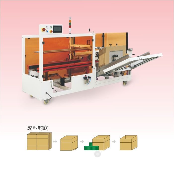
Hazard zones on a case erector
Walking the machine from blank feed to discharge shows where contact can occur. Each zone has a different hazard and a different guarding answer.
| Zone | What moves | Hazard | Primary control |
|---|---|---|---|
| Blank magazine and feed | Stack of flat blanks, lifting platform, feed guides | Hand or fingers caught between blank edges and frame; ejected blank if separation fails | Guarded feed opening, blank retention, separation aids, access interlock |
| Suction pick station | Vacuum cup, pick arm, vacuum generator or pump | Arm movement; cup pull; low-pressure trip; air-line hazard | Guarded enclosure, vacuum monitoring, controlled stop on pick failure |
| Plunger and forming section | Forming plunger, side belts, squaring frame | Crush and pinch as the blank opens into a tube; moving belts | Fixed guards over the forming frame; interlocked front access panel |
| Flap folding section | Folding plows, folder blades, compression arms | Pinch points on inner and outer flaps; spring-loaded folder return | Guarded fold area; timing and pressure checked in commissioning |
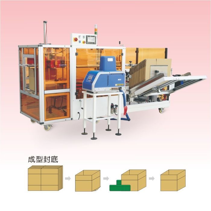
| Sealing station | Tape heads, crash plate, glue melter, hoses, nozzles or nail clinch | Tape head contact; hot adhesive burns; nozzle drip; nail feed | Station guarding, hot-surface labels, nozzle guards, dedicated controls per seal method |
| Discharge conveyor | Outfeed belt, transfer to case sealer or packer | Hand drawn into conveyor nip; trailing case contact | Conveyor guarding, nip-point covers, e-stop reachable from the discharge side |
Secondary hazards run across the whole machine. Compressed air at 0.5–0.7 MPa can whip a loose hose or blow debris; pneumatic exhaust can carry oil mist or board dust. Noise from cylinders, belts and the vacuum pump often sits in the 75–85 dB(A) range, which calls for hearing protection in older plants. Corrugated board sheds fiber and dust that can collect on guards, belts and electrical parts, and damp or curled blanks increase pick failures that tempt operators to reach in during a cycle.
Regulatory framework and standards
For machines placed on the EU market, the baseline is the Machinery Directive 2006/42/EC. It sets out the essential health and safety requirements that the machine must meet, and it requires the manufacturer to compile a technical file, carry out a risk assessment, issue an EU declaration of conformity and affix the CE marking before the machine is sold. The directive covers guarding, controls, emergency stop, materials, noise, instructions and the information the operator receives. A supplier exporting into the EU should be able to show the declaration and the supporting file; a buyer should ask for them before acceptance.
Harmonized and reference standards give the engineering detail behind the directive. The commonly applied set for packaging machinery includes the following. These are reference points for the risk assessment, not a checklist that substitutes for professional safety engineering.
- EN ISO 12100 — Machinery safety: general principles for design, risk assessment and risk reduction. It defines the hazard identification and risk-reduction sequence that the machine design should follow.
- EN ISO 13849-1 — Safety-related parts of control systems: design of safety circuits and performance levels. IEC 62061 covers the same field for electrical control systems using SIL ratings. Interlocks, light curtains and e-stop circuits are evaluated against these.
- EN 60204-1 — Electrical equipment of machines: supply disconnect, controls, protection, labeling and the IP rating of enclosures in the machine environment.
- EN ISO 14120 — Guards: general requirements for the design and construction of fixed and movable guards, including materials and opening dimensions.
- EN ISO 14119 — Interlocking devices associated with guards: principles for selection, mounting and function, including bypass prevention.
- EN 61496 — Electro-sensitive protective equipment such as light curtains, used where a physical guard would block access to the feed or discharge side.
- EN ISO 13850 — Emergency stop: principles for design and the layout of stop functions and stop controls.
Outside the EU, the reference framework differs. In the United States, OSHA 29 CFR 1910.212 sets the general machine-guarding requirement, 1910.219 covers mechanical power-transmission guarding, and conveyor safety follows ANSI B20.1. Buyers supplying plants in those markets should confirm which OSHA and ANSI provisions apply and whether the supplier’s guarding package meets them. In every market, the legal responsibility for conformity sits with the party placing the machine on that market, so the risk assessment and documentation should be reviewed locally rather than assumed from a CE mark alone.
Guarding design: fixed guards, interlocks and access
Guards on an erector fall into three practical types. Fixed guards cover zones that do not need regular opening: the top and sides of the forming frame, belt runs and the rear of the machine. Movable guards are hinged or sliding panels that open for cleaning, jam clearance and service; these carry interlocking devices that stop the hazardous motion when the panel opens. Electro-sensitive devices such as light curtains protect openings where a physical door would slow routine access, such as the feed or discharge side.
Guard design should follow the hierarchy in EN ISO 14120: guards must be firmly mounted, not easily bypassed, made of material that resists the machine environment, and arranged so the opening cannot reach a pinch or crush point. Amber or clear polycarbonate panels let operators see the cycle without opening a guard. Guards should not create new traps, and fasteners should not be removable by hand without a tool where accidental removal is a risk. Any guard removed during maintenance must be replaced before the machine returns to production; the operating manual should state this as a standing rule.
Interlocked guards are governed by EN ISO 14119. The interlock should stop the hazardous motion when the guard opens, and the machine should not restart until the guard is closed and the reset is initiated from a deliberate control. A bypass or override switch should be key-controlled or otherwise restricted to authorized setup and service use, and its use should be logged or visible on the HMI. Interlock switches themselves should be mounted so they cannot be defeated by wedging the actuator or taping the switch closed; magnetic-coded and separate-actuator designs reduce tampering compared with simple mechanical switches.
Safety controls: stops, resets and setup mode
The control system carries the safety functions that guards cannot cover alone. The emergency-stop layout follows EN ISO 13850: red mushroom-head stops on yellow backgrounds, reachable from the operator position and from both sides of the machine, wired into a safety circuit that removes hazardous motion without creating a new danger. The stop function should not rely on a PLC software command alone; safety relays or a safety controller monitor the circuit per EN ISO 13849-1 or IEC 62061.
After a stop caused by an interlock, jam or fault, restart must be a deliberate action at the HMI or a dedicated reset button, not an automatic resume. The reset should only be possible once the cause of the stop is cleared and the guard is closed. Setup and changeover work should use a hold-to-run or jog control at reduced speed, with the operator able to stop the motion instantly; a two-hand control may be specified where a hand must remain near a hazard during adjustment. The HMI should show active interlocks, fault history and vacuum or pressure status so an operator can diagnose a stop without opening a guard.
Light curtains at the feed or discharge side require a defined muting strategy if cases pass through; muting sensors should be arranged so the curtain does not blank out for a hand entering beside a case. Blank areas around the machine should keep the minimum distance set by the guarding standard, and warning signs should mark the reach-in zones even when a guard is closed.
Hot-melt adhesive and burn risk
Hot-melt systems heat thermoplastic adhesive to roughly 160–180 °C before feeding it through hoses and nozzles to the bottom flaps. At that temperature contact with skin causes immediate burns, and drips or strings can land on hands, clothing or nearby surfaces. The hazard sits in four places: the melter tank and barrel, the heated hoses, the nozzles and bead application point, and any accumulated adhesive on guards or the machine frame.
Machine-level controls should include insulated covers over hot surfaces, guards around the nozzle area, anti-drip nozzle design and visible high-temperature labels on the melter and hose routes. Hose routing should avoid pinching, abrasion and foot traffic, and fittings should be checked for leaks during planned maintenance. The adhesive supplier’s safety data sheet should be kept on site, together with the first-aid procedure for hot-adhesive burns: cool the area with running water, do not peel adhesive from the skin, and seek medical attention for serious burns. Operators working near the melter should wear heat-resistant gloves and eye protection; loose sleeves and jewelry should be kept clear of the nozzles.
During shutdown and cleaning, a defined bleed and cool-down sequence matters: pressure should be released before hose or nozzle work, and no one should open a hot system. Fumes from heated adhesive should be reviewed against the supplier’s data; where ventilation is poor, local extraction over the nozzle area prevents adhesive fumes and board dust from collecting in the breathing zone. Glue buildup on guards, belts and sensors should be cleared on the maintenance schedule so it does not become a fire or jam risk.
Noise, air supply and ejected blanks
Compressed air drives the pick, fold and compression cylinders, and a leaking or loose air line can whip under pressure. The machine should have an isolating air supply with a lockable valve, filter and regulator, and hoses should be secured so movement does not rub against frame edges. Exhaust ports should be pointed away from operator positions and from areas where board dust collects. The air-pressure requirement, typically around 0.5–0.7 MPa, should be stated in the manual so an undersized or contaminated supply does not cause erratic cycling.
Noise on an erector comes from cycling cylinders, the vacuum pump or generator, belts and blank separation. Where the measured level exceeds the local exposure threshold, hearing protection is required and the machine should be reviewed for noise reduction at the source: muffled exhausts, dampered guards and isolated pump mounting. Ejected blanks or double picks can leave cardboard pieces flying from the feed area; blank retention, separation brushes or air knives and a guarded feed opening reduce this risk, and operators should stand clear of the feed side during cycling.
Food-grade corrugated, tape and adhesive
When the packaged product is food, beverage, pharmaceutical or a consumer good that can contact the outside of the case, the packaging materials themselves fall under food-contact rules even though the case sits outside the primary package. Corrugated board, sealing tape, hot-melt adhesive and any printed coating should be assessed for the intended use, and the supplier should provide statements of compliance or food-contact declarations where required.
- EU framework: Regulation (EC) No 1935/2004 covers materials and articles intended to contact food, including paper and board components; specific measures and migration limits apply to certain materials. Confirm whether the board and adhesive meet the measures applicable to the product.
- US framework: FDA food-contact substance rules under 21 CFR govern adhesives, coatings and paper components that may contact food; verify the ingredient status and any required clearance for the intended packaging use.
- Paper and board: Recycled fiber grades may carry limitations depending on the food and the barrier between package and case; confirm board composition, starch or glue content, and whether dust or fiber shedding could transfer to product or packaging surfaces.
- Adhesives and tape: Hot-melt formulations, pressure-sensitive tape and any tape primer should match the food-contact status of the line; adhesive residue, strings and nozzle drips should be cleaned so they do not contact product or finished packaging.
Hygienic design follows the same logic as guarding: surfaces should be cleanable, moisture should not collect in dead corners, and enclosures should resist washdown where the plant is rinsed regularly. The enclosure IP rating per EN 60204-1 should match the washdown frequency; a dry warehouse machine needs less corrosion protection than one in a wet food plant. Board dust and fiber should be extracted or wiped from electrical enclosures, belt runs and guards on the maintenance schedule, since buildup affects both cleanability and fire risk.
Documentation, training and ongoing inspection
A compliant machine is supported by a document set the buyer can actually use. For EU-bound supply, the technical file behind the CE declaration includes the risk assessment, overall machine design, control-circuit description, guarding drawings, standards applied and test results. The delivered operating manual should cover intended use, hazards and residual risks, installation, electrical and pneumatic connection, changeover, fault response, planned maintenance, wear-part replacement and the lubrication schedule. Wiring and pneumatic diagrams should accompany the manual, along with a spare-parts list and the source of wear parts.
Operator training should cover the control layout, safe blank loading, interlock meaning, e-stop response, jam-clearing procedure, PPE requirements and the rule that guards stay closed during production. Maintenance staff need lockout/tagout procedures for service work: isolate electrical and pneumatic supply before opening panels or reaching into stations. A periodic inspection schedule should check guard fasteners, interlock function, e-stop circuit, hose and nozzle condition, belt and cup wear, and the integrity of warning labels. Keep a log of faults, interventions and replacements so recurring stops can be reviewed against the risk assessment.
Worked risk-assessment walk-through
To show how the standards apply in practice, take a common erector scenario: an operator loading blanks and watching the cycle at the front of a medium-speed tape machine. The hazard identification lists the possible contacts: fingers between blank edges at the feed, hand into the forming frame during a jam, contact with the tape head, and a loose item drawn toward the discharge belt. For each, the risk is rated by severity and exposure, then reduced in the standard sequence: eliminate the hazard first, then apply guarding and controls, then add information and training.
For the feed opening, elimination is not possible because blanks must enter the machine, so the design moves to guarding: a restricted feed opening sized so a hand cannot reach the pinch point, a blank retention stop and separation brushes or air knives. An interlocked panel covers the rear access to the forming section. For jam clearing, the manual defines a stop, isolation and lockout before any hand enters the frame, and a hold-to-run jog lets the operator feed a trial blank without continuous cycling. Residual risks that remain after these measures, such as standing near the feed side when blanks separate, are recorded in the manual as instructions for the operator. The same walk-through should be repeated for the glue build, where the hot-melt nozzle and melter add a burn consequence that changes the severity rating of any reach-in hazard.
Two checks follow the risk assessment into daily operation. First, every guard and interlock listed in the proposal should be present on the delivered machine, and each safety device should be tested during commissioning: open each panel and confirm the machine stops, trigger the light curtain and confirm the cycle interrupts, press each e-stop and verify the circuit drops out, then restart only through the reset control. Second, the site risk review should consider combinations the supplier could not know: line-side traffic, visitors passing the machine, maintenance access from above, and interfaces with neighboring equipment. These local conditions can call for extra barriers, floor marking or signage even when the machine itself meets its design standard.
Residual risks and safe working positions
No guarding removes every risk, and the manual should state the residual risks plainly. On an erector these typically include the need to stand clear of the feed opening during cycling, the requirement to isolate energy before service, the PPE expected near the glue system, and the instruction not to reach around guards to clear a slow belt or a misfolded flap. Operators should be positioned where they can observe the HMI and the forming station without leaning into a hazard, and routine tasks such as replenishing blanks or tape should be designed around a stable stance and two-handed access where possible.
Housekeeping feeds into safety as well. Board scraps, adhesive strings and tape tails collect around the feed and discharge; they are slip and trip hazards, and they can pull into belts or sensors. A clear area around the machine, scheduled cleaning and a defined waste bin keep the working zone usable and reduce the temptation to reach into a running station to free a small jam. Guards should be wiped so amber panels stay transparent enough to inspect the cycle visually, and labels should be replaced if they fade or peel so warnings remain legible.
Common compliance gaps on packaging machinery
| Gap | Why it fails | What to check in the proposal |
|---|---|---|
| Guards taped or tied open for convenience | Removes the physical barrier between operator and pinch points; defeats the risk reduction built into the design | Interlock design, tamper-resistant switch mounting, manual rule for guard replacement after service |
| Interlock bypassed or shorted during fault finding | Safety circuit disabled; machine restarts with access open, the most serious control-system failure | Bypass key control, logged override, safety-circuit monitoring per 13849-1 |
| Missing or poorly placed e-stops | Operator cannot stop motion quickly from the working position; stop relies on a non-safety circuit | Stop layout per 13850, safety relay or controller, reachability from both sides |
| Hot surfaces unlabeled or unguarded | Melter, hoses and nozzles reach burn temperature; drip contact causes injury | Insulated covers, nozzle guards, temperature labels, bleed procedure, SDS on site |
| No risk assessment or declaration provided | No evidence the essential requirements were addressed; conformity cannot be verified after delivery | Technical-file summary, declaration of conformity, standards list, manual and diagrams |
| Washdown construction not specified | Enclosures and materials corrode in wet food or chemical environments; dust and moisture collect | IP rating per 60204-1, stainless or protected construction, cleanable surface design |
| Food-contact materials undocumented | Board, tape or adhesive may not suit food or pharma packaging; migration and compliance unverified | Food-contact statements, adhesive and board declarations matched to product and market |
Pre-purchase safety checklist
- Destination market confirmed: EU machinery declaration, OSHA/ANSI references, or local rules that apply to the plant.
- Hazard zones mapped against the machine layout: magazine, pick, forming, fold, seal and discharge.
- Guarding package listed: fixed guards, interlocked movable guards, light curtains or other protective devices.
- Safety circuit described: safety controller or relays, performance level or SIL, e-stop and interlock wiring.
- Restart and reset behavior defined: deliberate reset at HMI, no automatic resume, setup hold-to-run control.
- Hot-melt controls addressed: insulation, nozzle guards, labels, bleed sequence, PPE, SDS and fume extraction where needed.
- Food-contact materials reviewed for the product: board, tape, adhesive, printed coatings and declarations.
- Documentation requested: risk assessment, declaration, manual, diagrams, spare list, training plan.
- Inspection and maintenance schedule included for guards, interlocks, e-stops, cups, belts and glue system.
- Site prep confirmed: isolating switch, air supply, floor space and access positions before installation.
How safety fits the wider line
The case erector family covers the standard and medium-speed builds referenced throughout this guide. The erector does not operate alone. It hands formed cases to a loading station and then to a case sealer or carton sealing machine, and the shared conveyor section carries its own nip-point guarding and stop requirements. On an integrated packaging line, safety circuits often connect across stations, so the erector’s interlocks, e-stops and reset logic should be compatible with the line control system rather than wired as an afterthought. Conveyor lengths and transitions are covered in the conveyor range, and machine-build references and certifications are summarized in the certifications and patents section.
For the mechanics behind these safety controls, see how the automatic case erector works through pick-off, forming, flap folding and sealing, and compare the three bottom-seal methods in the self-locking, tape and glue comparison. The brand-side equipment view is in the SunAura hot-melt glue case erector introduction, and budget implications are worked through in the case erector cost and TCO breakdown. Once the machine is running, the troubleshooting and changeover guide covers fault diagnosis and the maintenance intervals that keep guards and safety devices functional. Specific guarding or documentation questions can be sent through the contact desk with the destination market and product type.