
Palletizer Safety Starts Before the Robot Picks the First Case
Palletizer safety is the first question a packaging engineer asks when an end-of-line cell moves from concept to floor space, and it is the last thing a customer wants to discover during acceptance testing. A palletizing robot, a layer machine, or a gantry frame handles cases, bags, drums, and bulk loads at weights between 10 kg and 180 kg, moving through repeated cycles of lift, traverse, place, and return. The motion itself is predictable; the hazards around it are not. An operator who reaches in to straighten a skewed layer, a maintenance technician who climbs a fence to free a jam, or a pallet truck that crosses the discharge side of the cell can all be injured if the guarding and the safety circuit were sized wrong.
This guide lays out how SunAura Machinery approaches palletizer safety and CE compliance for end-of-line cells: the directives and standards that apply, how guarding is selected and spaced, how minimum guard distances are calculated, how collaborative robot force limits are checked, and what documents to expect at FAT and SAT. The numbers are planning bands to verify at factory acceptance, not a substitute for the builder’s own risk assessment under the applicable national regulation. If you are comparing cells, the sibling article on gantry vs robotic palletizer layouts covers how frame type changes the guarding envelope, and the operations guide on robotic palletizer troubleshooting and changeover covers the day-to-day faults guarding alone cannot prevent.
The Regulatory Framework: Machinery Directive and Harmonized Standards
For equipment placed on the EU market, the baseline legal instrument is the Machinery Directive 2006/42/EC. It does not prescribe a fence height or a stop distance directly; it requires the manufacturer to identify hazards, assess the risk for each hazard, and reduce that risk to an acceptable level through design, safeguarding, and information for use. The conformity route ends with a signed CE Declaration of Conformity, a technical file held for ten years, and the CE marking applied to the machine. Buying a palletizer with no Declaration, or with a Declaration that lists standards the cell was not actually built to, is a compliance gap that surfaces at the importer’s customs inspection or at a later labor audit.
EN ISO 13849-1: Safety-Related Control Performance Level
EN ISO 13849-1 rates the safety-related parts of the control system on a Performance Level from a to e, with PL d the typical target for robot cells that can cause serious injury and PL e reserved for the highest-risk functions. The rating accounts for category (single-channel or redundant channel), mean time to dangerous failure, diagnostic coverage, and common-cause failure. In practice this means the safety relay or safety controller, the interlock switches, the light-curtain inputs, and the emergency-stop circuit are evaluated as one chain, not as separate components. A cell that mixes a PL d sensor with a single-channel basic relay lands at a lower level than the sensor nameplate suggests, and the gap shows up in the control-system diagram in the technical file.
EN ISO 13855: Safeguarding Distance and Approach Speed
EN ISO 13855 is the standard that converts a device’s response time into a physical setback distance. It sets the approach speed used in the calculation, defines the reach-over and reach-under offsets, and gives the minimum separation between a safety device and the hazard zone. Every light curtain, safety scanner field, and guard opening on a palletizer cell has to be placed using these distances; mounting a curtain close to the robot because the floor plan is tight is the single most common non-conformance we see at FAT. The worked calculation further down in this guide shows how the numbers land for a typical robot cell.
EN ISO 10218-1 and EN ISO 10218-2: Industrial Robots and Robot Cells
EN ISO 10218-1 covers the robot itself: its protective stops, its brake behavior, its marking, and the limits of its own safety functions. EN ISO 10218-2 covers the integrated robot system: the cell, the gripper, the conveyors, the safeguarding devices, the interlocks, and the interaction with adjacent equipment. The distinction matters for procurement. A robot arm delivered from its manufacturer carries its own EN ISO 10218-1 compliance; the cell that packages that arm with conveyors, fence, and controls has to be assessed and safeguarded under EN ISO 10218-2 by the integrator. A buyer asking only for “robot certification” often receives the arm certificate without the cell-level assessment that actually governs the installation.
ISO/TS 15066: Collaborative Operation and Biomechanical Limits
ISO/TS 15066 supplements EN ISO 10218 for robots that operate without a full fixed fence, in power-and-force-limited collaborative mode or in speed-and-separation-monitored mode. It lists body regions and the quasi-static force and pressure limits that contact with a moving robot must not exceed, so that a clamp or a contact between operator and arm does not cause pain or injury. The force numbers in this guide come from that framework. A collaborative palletizer still needs a risk assessment; the standard defines the limits, it does not remove the requirement to design the contact away where possible.
Conventional Machine Standards: EN 619, EN 620, EN 1089
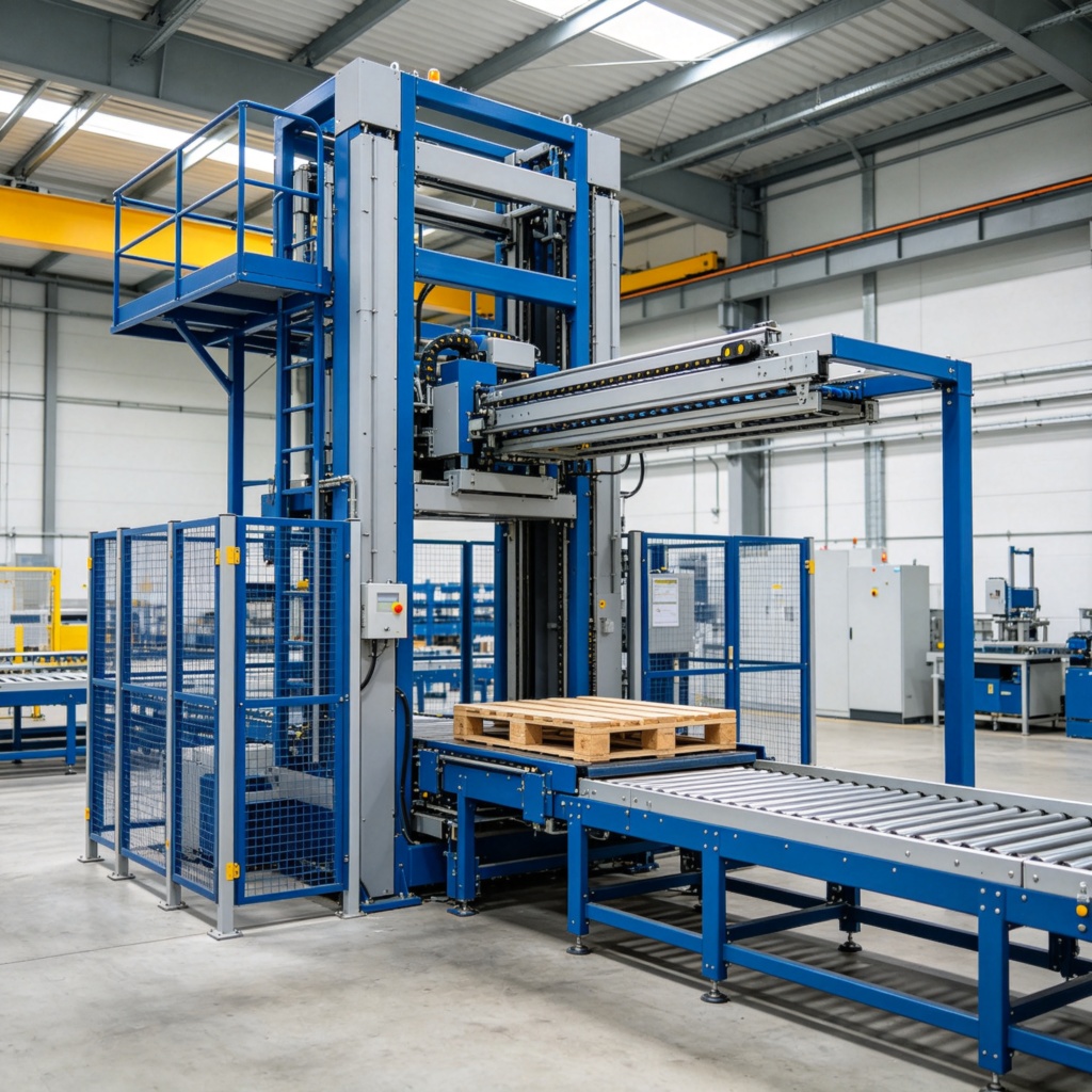
For conventional layer palletizers rather than articulated arms, the relevant standards sit alongside the robot standards. EN 619 covers mechanical handling equipment for unit loads, EN 620 covers continuous handling equipment for bulk materials, and EN 1089 covers safety requirements for palletizers and depalletizers in the conventional-machine family. A high-level layer machine with a mezzanine, a low-level case palletizer with a layer plate, and a gantry system each draw on this set for guarding of nip points, layer transfer zones, and discharge conveyors. When SunAura quotes a conventional machine, the technical file references the applicable standard in this group rather than forcing a robot standard onto equipment that has no articulated arm.
Hazard Analysis on a Palletizing Cell
The risk assessment starts by walking the cell in three states: normal production, setup and teaching, and maintenance or fault recovery. Each state produces a different set of exposures, and a guard that protects production may leave a maintenance path open. The hazard list we work through on every project covers the following points.
- Articulated arm sweep: the arm and gripper traverse a zone reachable from the feed, pallet-exchange, or discharge side. Sweep volume depends on reach, typically 2.4–3.2 m on a 120 kg or 180 kg class four-axis arm, and on the wrist tool.
- Nip and shear points: between layer plate and cases, forks and pallet boards, gripper fingers and a case, and conveyor guides and carton edges.
- Falling load: a dropped case, bag, or bulk bag from pick height; a pallet shifting on the build table; a cup releasing during traverse.
- Pallet handling: empty pallets from the stack magazine, full pallets exchanged by forklift or pallet truck, and the cell interface with the warehouse traffic lane.
- Pneumatic and vacuum energy: 5–6 bar air driving grippers, clamps, and pushers; vacuum holding a case by suction; residual air after isolation.
- Electrical and stored energy: servo drives, brake capacitors, and cable carriers still charged after the main disconnect opens.
- Reach-over and reach-under: access over a low fence, under a conveyor, or through a mesh opening even when the door stays shut.
For each hazard the assessment records injury severity, exposure frequency, avoidance possibility, and the safeguarding chosen. The hierarchy runs: eliminate the hazard by design, reduce risk by inherently safe measures, apply fixed or interlocked safeguarding, and add training, signs, and procedure last. Guards are not a substitute for moving a nip point out of reach.
Guarding Strategies: Fences, Interlocks, Curtains, Mats and Scanners
No single guarding device covers every access point. A palletizing cell typically combines several layers, each matched to how people actually approach the equipment.
- Fixed perimeter fence: mesh or panel fencing enclosing the robot sweep volume, the baseline barrier for cells where operators do not enter regularly. Mesh opening size and height follow the guarding rules in the applicable standard, sized to stop fingers, hands, and arms at the distance from the hazard.
- Interlocked access door: a hinged or sliding door with a guard lock or interlock switch. Opening it breaks the safety circuit and stops the motion; the lock can hold the gate closed until the robot reaches a safe state. Used where staff enter for pattern setup, gripper change, or fault clearance.
- Light curtain: an optoelectronic barrier across an open access point, usually the feed or discharge side. Cases and pallets pass through while a crossing body breaks the beam; resolution and mounting height are chosen for hand, arm, or whole-body detection.
- Safety laser scanner: a floor-plane scanner defining one or more protective fields where a fixed fence would block pallet-truck traffic or the access route changes between products. It triggers a stop on entry and can switch between warning and stop zones.
- Safety mat: a pressure-sensitive floor mat that cuts the circuit when stepped on. Simple to install and tolerant of rough pallets and spillage, but the mat edge must be guarded against reach-around.
- Emergency stop: red mushroom-head buttons at every station, along the fence, and on the pendant. The e-stop category and stop function are part of the EN ISO 13849-1 evaluation; an e-stop removes motion but does not release stored energy.
The choice between a fence and an open safeguarded side is driven by throughput and traffic. A cell running a single SKU at steady rate, like a conventional layer machine feeding a stretch wrapper, usually gets a full fixed perimeter with one interlocked service door. A compact carton cell that changes SKU often keeps feed and discharge sides open behind curtains or scanner fields, with robot sides fenced. A collaborative palletizer drops the perimeter fence but keeps the contact limits and separation monitoring described later.
Guard Distances: How Close the Hazard Zone Can Sit to the Safeguard
EN ISO 13855 sets the separation distance S between the safeguarding device and the hazard. The core formula for horizontal approach is S = K × T + C, where K is the human approach speed (1600 mm/s in the standard’s calculations), T is the total system response time in seconds, and C is an offset for reach-over or reach-under geometry. For horizontal reach the offset C is 850 mm; for reach-over from above, where a person leans over a barrier, the offset is 1200 mm. The result is the minimum setback; you add floor-plan tolerance on top rather than round the number down.
Worked example: a light curtain guards the pallet-exchange side of an articulated robot cell. The safety controller and robot stop give a combined response time T of 0.25 s from beam break to safe state. The curtain is mounted for horizontal reach at operator standing height. S = 1600 × 0.25 + 850 = 400 + 850 = 1250 mm. The curtain face must sit at least 1250 mm from the nearest point the arm or gripper can occupy; if the robot stop time were longer, say 0.40 s, the distance rises to 1600 × 0.40 + 850 = 1490 mm. A slower stop or a closer hazard forces a larger setback, which is why response time matters as much as fence height.
| Safeguarding device | Access geometry | Typical response basis | Minimum setback from hazard |
|---|---|---|---|
| Interlocked fence door | Side entry, door swings inward | Door opens circuit; robot stops on interlock signal | No reach-over if door and frame are guarded; door gap sized per guarding opening rules |
| Light curtain, full-body height ≥1200 mm | Horizontal approach, T = 0.25 s | 1600 mm/s approach + 850 mm offset | 1250 mm |
| Light curtain, lower guard height 900 mm | Horizontal approach with reach-under consideration | EN ISO 13855 table for reduced height | 900 mm minimum, measured to hazard |
| Safety laser scanner, protective field | Horizontal floor-plane approach | Scanner response plus robot stop, typical T ≈ 0.2–0.3 s | 700–1000 mm field setback, depending on stop time |
| Reach-over a barrier | Vertical reach from above | 1600 mm/s approach + 1200 mm offset | 1200 mm plus motion-distance term; fence height verified against reach length |
| Safety mat | Direct access at mat edge | Pressure switch response, T ≈ 0.1–0.2 s | Mat covers the entry point; sides guarded to prevent reach-around |
Opening dimensions follow the same reach logic. Finger-sized gaps between 0 and 350 mm reach depth are held to 12 mm or less; hand and arm openings grow larger only as the distance to the hazard increases. Mesh panels commonly use 50 × 50 mm openings when the panel sits far enough from moving parts that an arm cannot reach through to the hazard. If a panel is close to a gripper or a layer plate, the mesh specification tightens rather than loosens. These dimensions are checked against the guarding standard tables during FAT, not estimated from a stock fence catalog.
Cobot Palletizer Safety: Force and Pressure Limits Under ISO/TS 15066
A collaborative palletizer removes the perimeter fence, but it does not remove the hazard. In power-and-force-limited operation the robot moves at a speed and payload that limit contact energy, and any clamping or contact event must stay within the biomechanical limits in ISO/TS 15066. In speed-and-separation-monitored operation a scanner or vision system tracks the operator’s distance to the arm: the robot slows as the person approaches and stops when separation drops below the protective field. The two modes are sometimes combined, but the chosen mode has to be stated in the risk assessment.
The table below lists typical quasi-static force limits by body region from the ISO/TS 15066 framework. Treat these as the reference band for the cell’s contact assessment; the actual design target may sit lower for a region that the gripper can trap against the arm frame, and the pressure limit in N/cm² for that region also has to be checked against the standard. The cobot’s own payload and speed are matched to these limits: our collaborative cells run 10–25 kg payload (common 16–20 kg), 6–8 cycles per minute, and a ceiling of roughly 8–12 cases per minute, which keeps contact energy down compared with a 120 kg industrial arm.
| Body region | Typical quasi-static force limit | Contact scenario to check |
|---|---|---|
| Forehead / face | 130 N | Head contact with arm or gripper while reaching over the cell |
| Chest | 140 N | Torso pushed against frame or pallet during traverse |
| Abdomen | 110 N | Soft-tissue contact with wrist or tool at mid-height |
| Upper arm | 160 N | Arm pinned between link and cell structure |
| Palm | 260 N | Hand contact with gripper body or suction pad frame |
| Back of hand | 140 N | Knuckle contact during tool approach to the case |
| Thigh | 220 N | Leg contact at low robot height near pallet level |
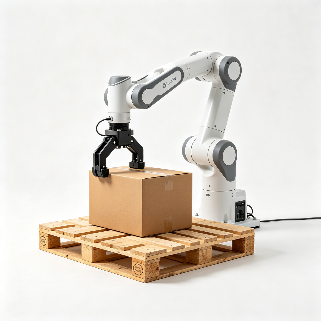
Two engineering rules follow from these limits. First, eliminate clamping geometry wherever possible: gripper fingers and frame members should not form a trap that can close on a finger or limb, because a contact that stops against a flat surface dissipates force, while a trap concentrates it. Second, verify the force on the actual tool. The robot arm’s listed collaborative rating does not carry over automatically to the gripper, vacuum frame, or finger extension; the complete wrist assembly has to be included in the contact assessment. A cobot with an overhung tool that adds mass at the wrist changes both the inertia at contact and the reachable volume.
Safety Circuit Architecture: Performance Level, Channels and Diagnosis
The safety circuit is evaluated as a chain from sensor to stop actuator. A typical palletizer cell chains the following inputs: interlock switches on fence doors, light-curtain outputs, scanner protective-field signals, e-stop buttons at stations and pendant, and any enabling device on the teach pendant. The chain feeds a safety relay or safety controller, which drives the robot’s safe stop function, stops conveyor motion in the guarded zone, and switches off pneumatic releases where required.
For a cell that can cause serious injury, we design to PL d under EN ISO 13849-1, usually with redundant channels and channel monitoring so one channel fault does not disable the safety function. PL e is used where consequence is severe and exposure frequent; PL c suits lower-risk functions such as a guard door on a low-energy auxiliary station. The circuit diagram shows each device’s category, channel count, diagnostic coverage, and the resulting PL of the complete chain. If the buyer’s safety officer asks for a PL target, that target should be answered component by component in the quotation rather than as a single label on the fence.
- Safe stop function: defined per the robot’s stop category, with brake engagement checked after the stop command.
- Reset logic: after a guard opens and closes, the machine does not restart on its own; an explicit reset at the operating station confirms the zone is clear.
- Mode selection: production, setup, and maintenance modes switch speed limits and enable guarding behavior; the mode key or selector is itself a monitored control.
- Diagnostics: channel faults, device faults, and bypass states are reported to the HMI and logged, so a defeated curtain is visible rather than silent.
CE Conformity: Risk Assessment, Technical File and Declaration
The CE mark is the end of a documented process, not a sticker applied at shipment. The conformity route under the Machinery Directive 2006/42/EC gathers into the technical file: the risk assessment and residual-risk notes, arrangement and guarding drawings, the control-system safety diagram with performance levels, the standards list, safety-device certificates, electrical and pneumatic schematics, manuals in the destination language, and the final Declaration of Conformity.
At the buyer’s site, the installation changes the risk picture again. A cell guarded as a standalone machine now connects to incoming conveyors, an outfeed wrapper, forklift traffic, and routines that did not exist in the workshop. The site needs its own check: conveyors guarded where they pass the cell, floor markings for the traffic lane, access points matching the as-built layout, and a residual-risk review closing the loop between builder documentation and installed condition. The builder’s Declaration of Conformity covers the machine as delivered; the integrator or site owner remains responsible for the installed system where equipment is combined on the floor.
SunAura’s own certifications, patents, and test records are listed on the certifications and patents page for buyers verifying supplier evidence before an order. For the machine itself, the practical checklist at acceptance covers the items in the next section; we treat missing documentation as a hold point, not as paperwork to follow after shipment.
Machine-by-Machine Safety Notes
Low-Level Case Palletizer
A low-level case palletizer builds layers at roughly standing or pit level, which keeps the operator close to the layer plate and the case infeed. The guarding focus is the layer-transfer zone, the squeeze between cases and side guides, and the interlocked door used to clear jams. Because access is at floor level, reach-under and reach-over gaps around the fence get the closest scrutiny; a low panel that lets someone lean in over the top fails the setback check even if the mesh itself looks fine.
High-Level Layer Palletizer
A high-level layer palletizer feeds cases at height and drops layers onto a pallet below, needing roughly 4.5 m of ceiling height plus a mezzanine. The safety case splits into two zones: the upper platform where the layer mechanism runs, and the under-machine zone where pallets are built and discharged. Stair and mezzanine access needs its own interlocks and rail guarding, and the under-machine opening must be fenced so nobody stands beneath a dropped load. Conventional layer machines run 1–3 layers per minute on steady single-SKU throughput; that lower cycle rate does not reduce the guarding requirement, it changes which hazards dominate.
Collaborative Robot Palletizer
The collaborative robot palletizer is the fence-free layout, sized for lighter cases and bag stacks at 10–25 kg payload and an 8–12 cases per minute ceiling. Its safety documentation leads with the ISO/TS 15066 contact assessment, the chosen collaborative mode, the gripper contact review, and separation monitoring where fitted. Where the product is heavier or the cycle faster than the cobot’s contact limits allow, the correct answer is an industrial arm in a guarded cell, not a cobot outside its rated mode.
Gantry Palletizer System
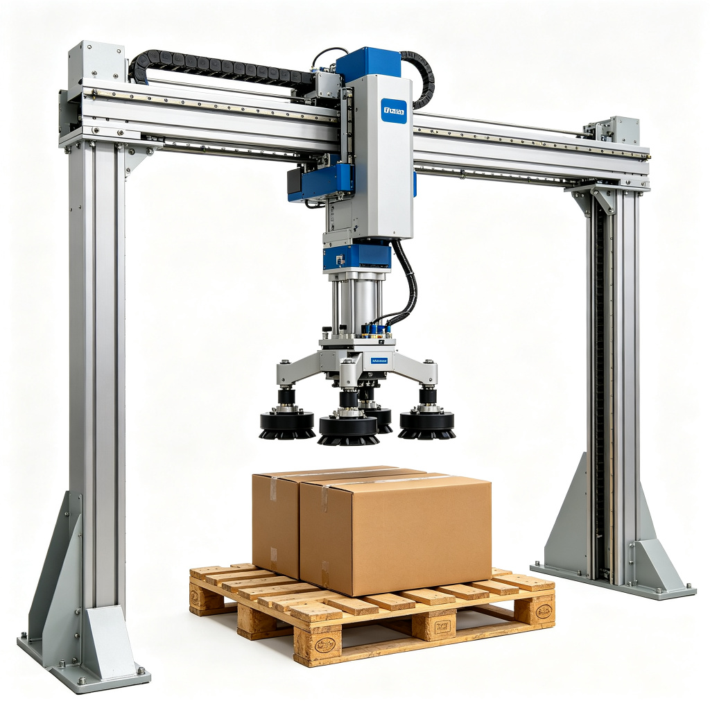
A gantry palletizer system travels on fixed Cartesian axes with a rigid Z axis and a 3–4 m travel envelope. Its guarding envelope is simpler in plan than an articulated arm’s sweep, because the frame defines the motion volume, but the vertical fork and vacuum rail create overhead and nip points along the whole travel. Fixed guards cover the frame sides; interlocked access covers pallet exchange; any walkway beneath the travel path needs dropped-load protection. The full palletizer family, including these four layouts, is indexed on the palletizers product index.
FAT and SAT Safety Checklist
Factory acceptance tests the cell in the builder’s workshop; site acceptance repeats the check after installation and connection to the line. The safety items on both checklists follow the same order.
- Verify the risk assessment covers the as-built configuration, including gripper, feed conveyor, and pallet exchange.
- Check every interlock switch and light curtain: open or break each one, confirm the robot stops and the HMI reports the fault, confirm restart requires a manual reset.
- Measure guard setbacks against the EN ISO 13855 calculation: curtain or scanner distance to the nearest hazard point, fence panel distance to moving parts, opening dimensions against reach tables.
- Test all e-stop buttons around the cell, including the pendant, and record stop time and brake behavior.
- Confirm the safety circuit performance level against the control diagram; trace each input channel through to the stop actuator.
- Run the collaborative cell through the contact scenario list; confirm force and pressure stay inside the ISO/TS 15066 limits for the loaded gripper, not the bare arm.
- Verify lockout and isolation: main disconnect, air isolation, residual-energy release points, and the posted LOTO procedure for maintenance.
- Confirm manual, setup, and production modes switch speed and guarding behavior as designed.
- Check documentation: Declaration of Conformity, standards list, schematics, manuals in the required language, and residual-risk notes.
- Review the installed site layout: traffic fencing, conveyor guards at the cell boundary, and any residual risk added by connecting adjacent equipment.
Common Non-Conformances That Stop Acceptance
From our own FAT history, the gaps that delay sign-off cluster in a short list. Buyers and engineers can use it as a pre-audit checklist before the inspector arrives.
- Light curtain mounted closer to the hazard than the calculated setback to save floor space; fix by moving the curtain or slowing the stop time so the original distance becomes valid.
- Interlock switch bypassed or wired as a signal contact, so opening the door reports a fault but does not stop the arm.
- Fence mesh sized for fingers while the panel sits close enough for a whole hand to reach through to the gripper.
- Cobot assessment written for the bare arm, leaving the gripper, suction frame, or finger extension out of the contact review.
- Safety relay chosen at a lower category than the sensors, pulling the whole chain below the target PL.
- No reset logic after a guard opens, so the cell restarts automatically when the door closes.
- Technical file missing the cell-level EN ISO 10218-2 assessment, with only the arm manufacturer certificate supplied.
- Residual air or stored servo energy not isolated in the maintenance procedure, so LOTO cannot be secured before work starts.
Operator Training, Lockout and the Residual Risks the Guard Cannot Remove
Guarding reduces risk; it does not replace instruction. Operators need training on the cell’s cycle, the meaning of each HMI fault state, the locations of e-stops, and the rule that no part of the body enters the swept zone while the robot is in production mode. Maintenance technicians need the lockout/tagout procedure: isolate electrical supply, isolate compressed air, release residual vacuum and pneumatic pressure, confirm zero motion before opening the fence, and verify safe state before any hand enters the gripper zone.
Some residual risks stay on the machine even after design and guarding. Reaching in to clear a jam always requires stop and isolation, never a hand at moving cases. Pallet exchange in a mixed-traffic lane needs traffic rules so a forklift does not enter the cell zone while the arm cycles. Tooling change between products follows the changeover sequence in the operations guide, with the robot held safe and air isolated where the gripper is touched. These residual risks are written into the manual and marked on the machine, not assumed away by a guard rail.
How the Rest of the Cluster Connects
Guarding decisions tie back to layout and throughput. The comparison between gantry and articulated-arm palletizer layouts shows how reach and frame type change the swept volume and therefore the fence plan, and the launch note on the dual-station robotic palletizer explains where a second build position adds pallet-exchange traffic that the safety layout must account for. On the operations side, the guide to robotic palletizer troubleshooting and changeover covers the faults and periodic maintenance that keep a compliant cell running safely after acceptance. Every machine in the end-of-line range, from low-level case machines to heavy-duty arms, is listed in the palletizers product index.
When you evaluate a palletizer quote, ask for the risk assessment, the safety circuit diagram with performance levels, the guard-distance calculations, and the standards list before comparing price. A cell that produces cases quickly but cannot show those documents carries a compliance cost behind the machine price, and that cost usually lands at acceptance or the first audit, not at the order stage. Our engineering team works through the same questions with buyers at inquiry stage, matching the guarding envelope to product mix, floor layout, and traffic around the cell before the layout is locked.