
How a Robotic Palletizer Works: Axes, Payload, Reach, Cycle Time and Layer-Pattern Math
A robotic palletizer takes individual cases, bags or bundles from an infeed conveyor and stacks them in programmed layers on a pallet, one pick at a time. Understanding how a robotic palletizer works means following the machine from the product arriving at the pickup point through each axis of motion, the payload rating that limits what the gripper can carry, the reach envelope that defines where pallets can sit, the cycle time that sets cases per minute, and the pattern math that decides where each case lands on each layer. This deep dive goes through those subsystems with concrete numbers: payload in kilograms, reach in millimeters, cycle in seconds, picks per hour, air consumption in Nl/min, and layer counts on a standard pallet. The reference machines are the articulated arms in the SunAura palletizer range; figures are planning bands to verify at factory acceptance, not fixed quotations.
The machine most people picture when they say “robot palletizer” is a four-axis articulated arm on a floor pedestal, carrying a vacuum or clamp gripper, working between a feed conveyor and one or two pallet build positions. A collaborative robot cell is a lower-payload variant of the same idea, and a gantry machine solves the same stacking task with straight rails instead of rotary joints; the motion principles below apply to the arm first, with notes on where the variants diverge.
The Anatomy of a Robotic Palletizer Cell
Before the axes make sense, look at the cell as a set of connected subsystems. Every robotic palletizer installation contains the same pieces in some form:
- Infeed conveyor: carries product to the pickup point, usually with side guides that square the case and a photoeye that signals the robot when a pick is ready.
- Robot arm and pedestal: the articulated arm, bolted to a reinforced floor pad, with controller cabinet and teach pendant beside it.
- Gripper tooling: vacuum beam with suction cups for cartons, clamp or fork tool for bags, or a frame tool for bulk bags; mounted to the wrist flange.
- Pallet build positions: one or two stations where empty pallets are presented and finished stacks leave the cell, sometimes with an empty-pallet stack dispenser and slip-sheet option.
- Control and communication: the robot controller runs the motion program and exchanges case-present, pallet-count, fault and cycle signals with the line PLC.
- Guarding: perimeter fence, interlocked gates, light curtains or safety scanners that stop motion when someone enters the working envelope.
- Discharge path: conveyor, roller track or forklift lane that carries the finished pallet toward stretch wrapping.
The arm itself is only the middle of that chain. A fast arm still cannot stack product the conveyor cannot feed, and a tall stack still leaves the discharge lane if the finished pallet cannot leave the cell on time. When a cell underperforms, the bottleneck is often one of the conveyors or the pallet exchange, not the arm.
Axes: How the Arm Moves
A palletizing-class articulated arm carries four axes. The base rotates the whole arm around the pedestal; the shoulder joint lifts the upper arm; the elbow joint folds the forearm; the wrist keeps the gripper level through the lift, so the product stays upright whether the arm reaches low over the conveyor or high over the finished stack. The controller coordinates all four joints together so the gripper travels in a straight-line path between the pick point and each pallet cell, rather than tracing an arm arc that would swing the load sideways.
Four axes are enough for palletizing because the task repeats a small set of motions: reach out to the conveyor, descend onto the product, grip, lift, transfer over the pallet, place, release, retreat. A fifth or sixth axis, typical for welding or handling jobs, adds wrist roll and tool orientation that case stacking rarely needs. The arm’s servo motors drive each joint through gearboxes; encoders report joint angle back to the controller, which calculates gripper position in Cartesian coordinates against the taught pickup and pallet positions.
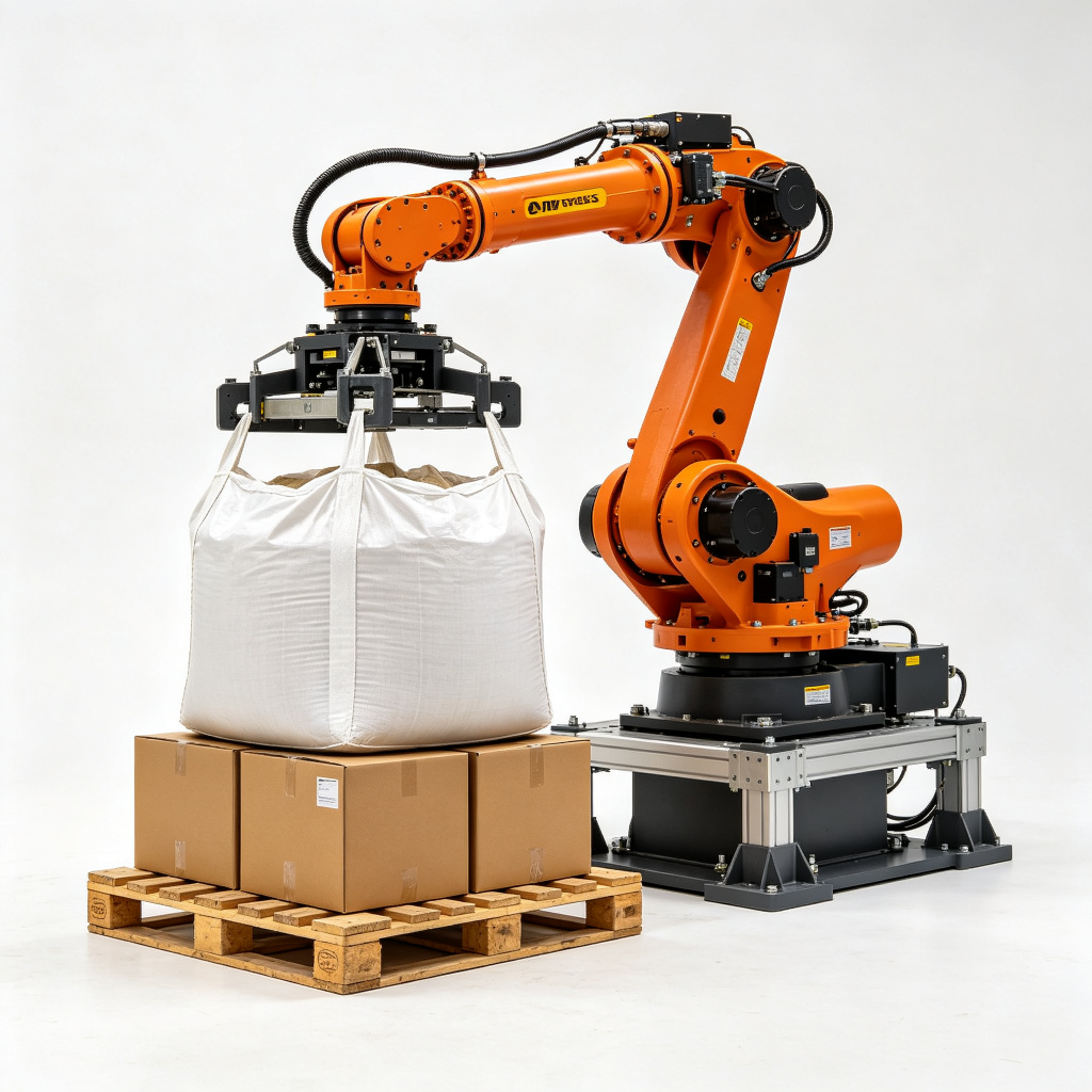
The standard reference machine in this architecture is the four-axis robotic palletizer 120 kg, built for cartons, trays and sacks in the regular payload class. Heavier duty moves to the heavy-duty robotic palletizer 180 kg, where joint drives, linkages and wrist bearings are sized for bulk bags and dense bundled loads.
Payload: What the Number Actually Limits
Payload is the maximum total weight the wrist can carry, and it includes the gripper tool, not only the product. If a vacuum beam weighs 18 kg and a carton weighs 16 kg, the wrist sees 34 kg at that pick; if a clamp tool weighs 45 kg and a sack weighs 40 kg, the pick is 85 kg. The machine’s payload rating has to cover the heaviest product plus the tooling, with margin for the dynamic forces of lifting and stopping. Two standard classes cover palletizing duty: 120 kg for cartons, trays and regular bags, and 180 kg for bulk bags, dense bundles and heavier industrial loads.
Two qualifications keep the payload number honest. First, payload de-rates toward the outer edge of the reach envelope: the same arm that carries the full rating near the pedestal may shed capacity at the far reach, because the joint moments rise with lever arm. Second, payload is rated for repeated cycles, not one-off lifts. A tool that sits at 95% of the rating on paper will wear the joint gearboxes faster over two shifts a day, so the planning rule is to keep product plus tooling comfortably inside the class rather than at the edge. For a bulk-bag application, weigh the empty FIBC, the filled product and the frame tool separately, then add them before selecting the 180 kg class over the 120 kg one.
Reach and the Work Envelope
Reach is the horizontal distance the arm can cover from the pedestal center, typically 2.4–3.2 m depending on model. Around that center the arm sweeps a circular envelope; inside it, the gripper can reach the conveyor pickup point and every pallet cell on the build positions. Vertically, the envelope covers from a low place-down height to the top of the finished stack plus gripper retraction; the top of a 1200 mm pallet loaded to a 1800 mm stack, plus gripper height and lift clearance, sets the vertical demand on the arm.
Layout practice keeps pallet centers inside the comfortable reach band rather than at the rated maximum. A position at the far 20% of the reach costs cycle time and payload margin, and it puts the arm in a stretched posture that transfers more load into the joint bearings. When three stations — one conveyor and two pallets — do not fit inside one envelope, the options are to relocate the pedestal, split the task across two arms, or choose a longer-reach model in the next size up. The gantry alternative covers a fixed 3–4 m rectangular span instead of a circular radius; the comparison between the two layouts is set out in the gantry vs robotic palletizer guide.
Cycle Time: The Anatomy of One Pick
A palletizing cycle is the full repeat from one ready product to the next ready product released on the pallet. Typical cycle time on a four-axis arm runs 3.5–6 s per pick, depending on reach distance, product weight, gripper type and settle time. At those cycle times, single-pick output runs 700–900 picks/hour, climbing toward roughly 1200 picks/hour when motion is optimized: pallet positions close to the conveyor, a gripper matched to the product face, and no unnecessary dwell after the arm stops.
Break one cycle into its motion segments. The arm starts parked above the pallet or in a home position; it moves toward the pickup point; it descends onto the product; the gripper grips or seals; it lifts clear of the conveyor; it transfers over the target pallet cell; it descends to place; it releases; it retreats to height. Each segment has a travel distance and a speed limit set by the controller’s motion profile, and the dwells at grip and release add a fraction of a second where the load has to be confirmed secure before motion continues.
| Cycle segment | Typical share of cycle | What determines the time |
|---|---|---|
| Retreat and approach to pickup | ~20–25% | Distance from home or last pallet cell to conveyor; arm acceleration limits |
| Descent and grip | ~15–20% | Descent speed, seal or clamp confirmation, settle time |
| Lift and transfer over pallet | ~25–30% | Horizontal distance between conveyor and pallet cell; payload dynamic limits |
| Place, release and retreat | ~20–25% | Place-down height, release confirmation, clearance above neighboring cases |
| Dwell and sensor confirmation | ~5–10% | Pick confirmation, vacuum check, cell-position settle |
When a cycle runs longer than the 3.5–6 s band, the usual causes are a pickup point too far from the pallet, a gripper that has to re-seal after a weak vacuum, an arm that drifts before the descent, or pallet exchange that interrupts the arm between layers. Measuring each segment on the teach pendant’s cycle report shows which one is eating the time.
Layer-Pattern Math: Where Each Case Lands
The pattern program divides the pallet top into a grid and assigns each case a grid cell, an orientation and a layer. The math starts with three measurements: case length and width, pallet usable length and width, and the target cases per layer. Cases sit with a small gap between neighbors so layer joints do not collide, and rotated cases alternate orientation between layers to lock the stack against shifting.
Worked pattern: 400 × 300 mm cases on a 1200 × 1000 mm pallet
Take a carton 400 mm long by 300 mm wide on a 1200 × 1000 mm wooden pallet, usable surface roughly 1180 × 980 mm after edge clearance. Lay the cases lengthwise across the 1180 mm direction: three cases at 400 mm give 1200 mm, which is slightly over, so two across at 400 mm plus a re-orientation column is the usual split. Along the 980 mm depth, three rows at 300 mm give 900 mm with clearance left at the edge. A mixed-orientation layer runs four cases in one direction and two in the rotated column, totaling six cases per layer; the next layer rotates the pattern so joints between cases break over the cases below, which keeps the pallet square through stretch wrapping. At six cases per layer and eight layers per target stack, the finished pallet carries 48 cases; the controller tracks cell count, layer count and pallet count as the cycle repeats.
Worked pattern: rotated cases and joint breaking
Where box dimensions leave leftover space that a straight grid wastes, the pattern rotates selected cases 90° to fill the layer tighter. Rotation uses the wrist orientation to turn the case between pickup and placement; each rotated cell adds a short wrist turn to the cycle, which should be counted in the segment timing above. The controller stores the full pattern as coordinates: case center X and Y on the pallet, rotation angle, layer number, and the next cell in sequence. A different carton size calls a different recipe; the machine does not re-derive the grid at runtime unless the line is set up for mixed case sizes on one pallet.
Pattern capacity per layer depends on case footprint, not arm speed: two lines with the same arm can run different cases/min simply because one pattern fits eight cases per layer and the other five. When a line plans a new SKU, the pattern should be laid out on paper first — cases per layer, layers per pallet, total cases per pallet — before the cycle rate is quoted.
Gripper Types and Air Consumption
The gripper is the interface between the arm and the product, and its design sets both the vacuum demand and the fault rate. Three gripper families cover most palletizing duty:
- Vacuum beam: suction cups or a foam pad seal on the top face of a case; one cup per case face or a full-width pad for multi-case picks. Best for regular cartons with flat, sealed board.
- Clamp tool: two paddles close on the sides of a bag or bundle; used where the top face cannot hold a vacuum, such as woven sacks or loose bundles.
- Frame or loop tool: hooks or bars engage the loops of a bulk bag; required for FIBC lifts in the 180 kg class.
Pneumatic vacuum grippers draw roughly 40–80 Nl/min average at a 5–6 bar supply, depending on cup count, leak rate and how often the vacuum cycles. The compressed air line to the cell must carry that demand plus any clamp actuation or push-button air in the guarding circuit. A porous corrugated board, a printed or dented face, or a case with an open top can leak enough that the cup does not hold; in those cases the tooling moves to a clamp, or the pad switches to a wider foam seal that compensates for small gaps. Vacuum presence is confirmed by a sensor before the lift; a weak seal triggers a re-grip attempt or a fault stop rather than a dropped case traveling over the pallet.
Sensors and Product Detection
The cell runs on a small set of signals. A conveyor photoeye detects the case at the pickup point and tells the controller the product is squared and ready; a vacuum or clamp sensor confirms grip before lift; a pallet-position sensor checks that an empty pallet is seated at the build station; layer and cell counters track progress against the recipe. On dual-station cells, a station-ready signal tells the arm which pallet can accept the next cell, and a pallet-complete signal calls for exchange.
Most mispicks trace back to one of three sensor conditions: the case was off-center when the photoeye fired, the seal failed on a porous face, or the pallet shifted between layers. Fault response in the controller is tiered: retry the grip once, move the product to a reject position, or stop the cell and call the operator. The fault-to-cause-to-fix walkthroughs, including dropped cases and skewed layers, are collected in the robotic palletizer troubleshooting and changeover guide.
Throughput: Converting Cycle Time to Cases per Minute
Throughput math starts from the cycle. A 4.5 s average cycle gives 3600 / 4.5 = 800 picks/hour, or about 13.3 cases/min if every pick carries one case. A 6 s cycle drops to 600 picks/hour, 10 cases/min; an optimized 3.5 s cycle reaches about 1028 picks/hour, 17.1 cases/min. These are single-pick numbers. A gripper that lifts two cases per pick doubles the cases per cycle, but only when the case dimensions and vacuum seal support a multi-case beam.
Worked line: 200 cases/hour
A line feeding 200 cases/hour runs about 3.3 cases/min. Even a conservative 6 s cycle holds 600 picks/hour, so a single-station arm clears the rate with headroom for pallet exchange and occasional re-grips. The cell should still be checked against exchange time: a finished pallet that takes 40–60 s to leave and an empty to arrive pauses the arm during that window, and that lost time has to fit inside the headroom above line demand.
Worked line: 600 cases/hour
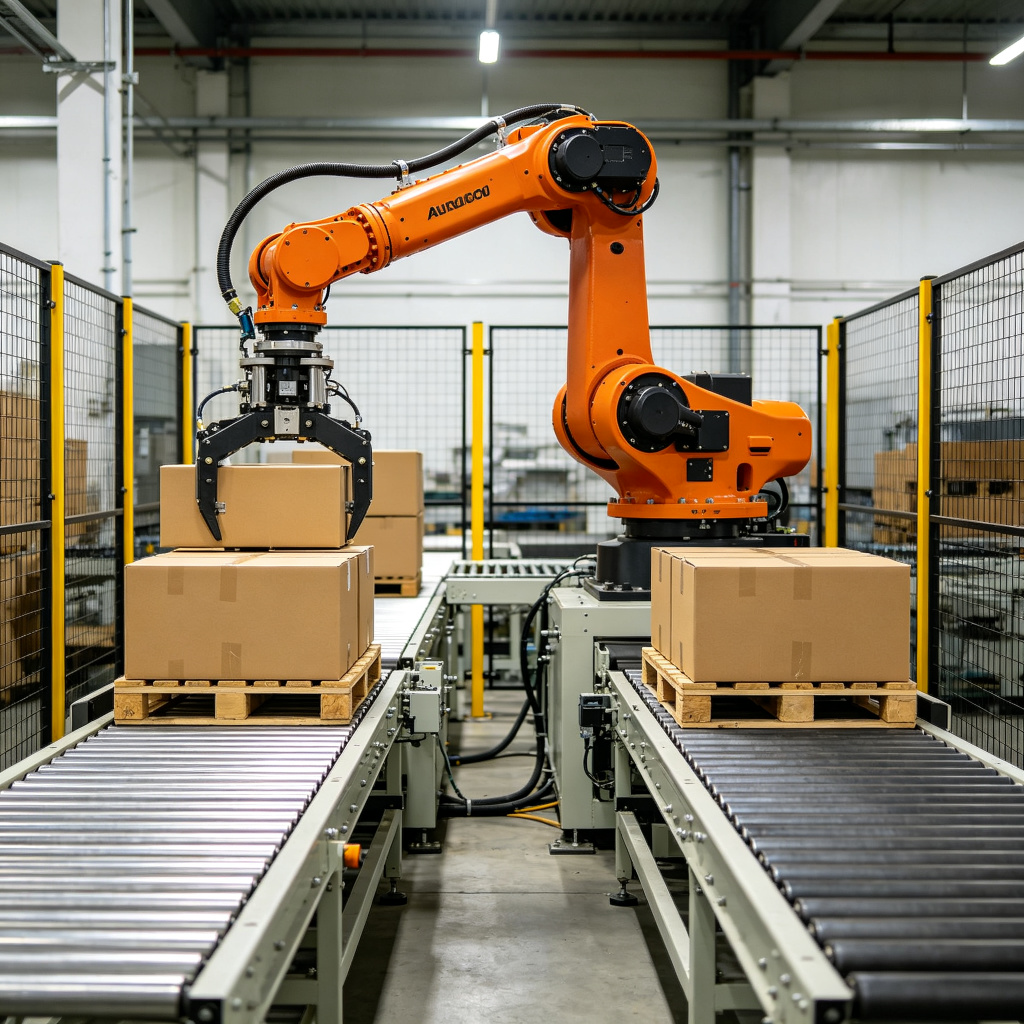
A 600 cases/hour line runs 10 cases/min, which sits at the slower end of the arm’s optimized band. At this rate, single-station exchange becomes the bottleneck: every pallet change steals time the arm cannot recover from cycle speed alone. A dual-station arrangement puts two build positions inside the reach, so the arm keeps stacking on one pallet while the other is exchanged; effective output can approach roughly 1.6–1.9 times a single station at the same pick rate. The dual-station robotic palletizer is the reference cell for this arrangement, with the arm working between two conveyors or pallet build positions rather than waiting on one.
Programming, Recipes and Changeover
The motion program is written once during commissioning: pickup position taught, pallet positions taught, pattern grid laid out, gripper and sensor conditions configured. Each product SKU is then stored as a recipe — case dimensions, pattern, cases per layer, layers per pallet, gripper selection. A changeover between recipes is a selection on the teach pendant or line HMI, not a mechanical rebuild; once the gripper suits the new case face, recipe changes run in single-digit minutes. Cases that need a different gripper, such as a switch from cartons to bulk bags, add tool-change time that should be estimated separately and written into the production schedule.
Recipe data should match the real product drawings: case dimensions, weight, face condition, and whether the case seals flat enough for vacuum. A recipe entered from an approximate box size produces skewed layers before it produces anything else. Keep the pattern library clean, one recipe per SKU, with the case drawing revision noted so a packaging change does not run against an outdated grid.
Load Families the Arm Handles
- Cartons and trays: vacuum grip on the top face; the 120 kg class covers standard shipping cases at normal line rates.
- Woven and paper bags: clamp or fork tool; bag irregularity means the arm squares the load over the pallet before descent.
- Drums and jugs: clamp or harness tool centered on the load; check payload and reach before selecting the class.
- FIBC bulk bags: frame tool on the 180 kg class; combined bag, product and tool weight confirmed against the de-rated payload at reach.
Where the Cobot and Gantry Variants Diverge
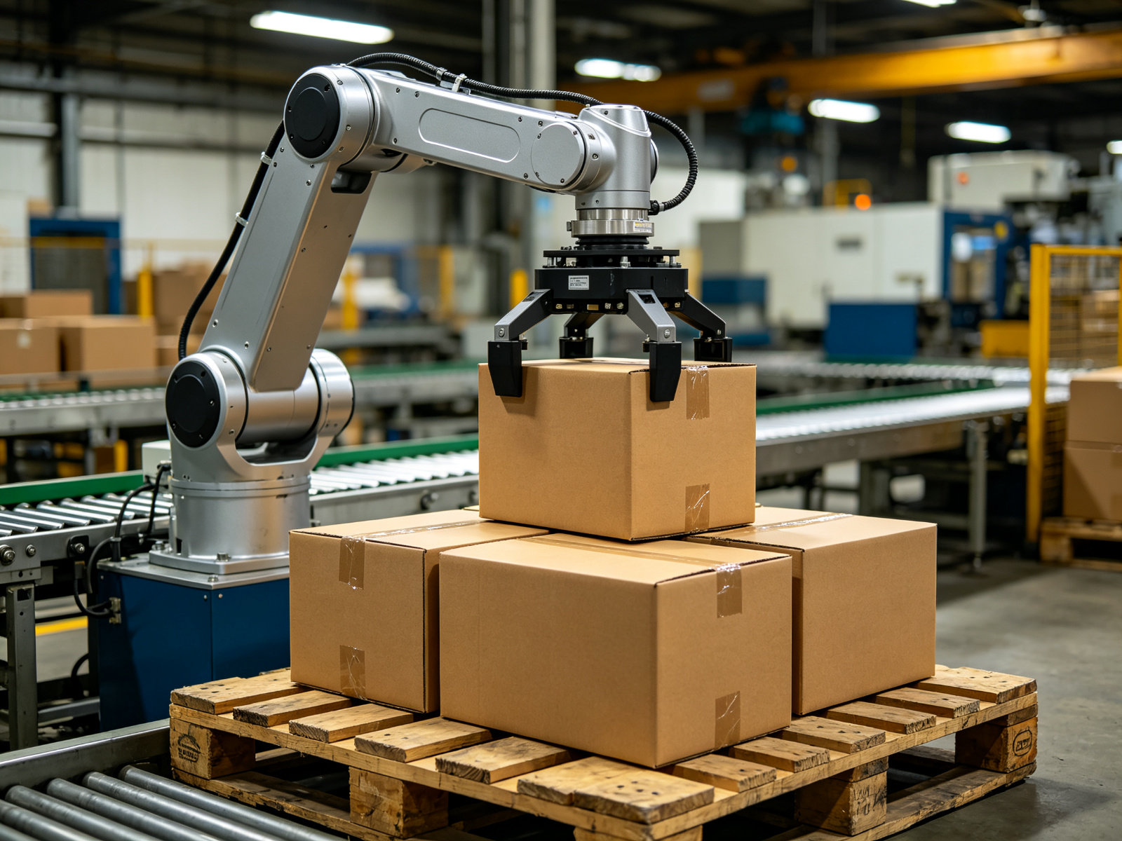
The collaborative robot palletizer trades payload and rate for low guarding demand. Cobot arms run a 10–25 kg payload range, most commonly 16–20 kg, with a throughput ceiling around 8–12 cases/min and roughly 6–8 cycles/min. Under a power-and-force limited collaborative application, the cell can run without a full perimeter fence when the task passes the relevant collaborative safety assessment. The cycle math is the same — approach, grip, lift, place, release — but the payload and reach bands are narrower, and the cobot is sized for small boxes and low-rate mixed cells, not heavy bags or high-rate carton lines.
The gantry palletizer system keeps the same pick-and-place sequence but moves the gripper on fixed X, Y and Z rails over a 3–4 m rectangular span. Its axes are straight-line rather than rotary, its settle time is short on a rigid frame, and its guarding envelope is a fixed volume. The trade-off is layout rigidity: gantry positions are fixed to the frame, while an arm serves stations around a circular envelope. Which geometry fits a given line is the subject of the dedicated comparison in the gantry vs robotic palletizer guide.
Utilities, Floor Space and Installation
Site preparation for an arm cell covers floor, air, power and signal. The pedestal bolts to a reinforced pad rated for the reaction forces of a 120–180 kg load at reach; the guarding posts anchor around the sweep envelope. Compressed air arrives at 5–6 bar, sized for the gripper’s 40–80 Nl/min average vacuum demand plus clamp actuation. Electrical supply feeds the arm drives, controller cabinet and guarding circuit; power draw depends on arm class and cycle duty, and should be confirmed against the machine datasheet rather than estimated from conveyor loading. A network or hardwired signal link connects the cell to the line PLC for case-present, pallet-count and fault signals.
Installation, freight and site acceptance testing add roughly 12–22% on top of the machine-only price for a standard cell. The SAT sequence runs empty-case cycles first to confirm motion and pattern, then real product at production rate, with cycle reports and pick-success rates recorded before sign-off. Machine-only price bands and the full cost breakdown, including labor baseline and payback assumptions, are laid out in the companion robotic palletizer cost and TCO guide.
Reading the Machine’s Own Numbers
Once the cell runs, the controller exposes the same parameters this article has used, and the operating team should know which ones matter. Cycle time per pick shows whether motion stays in the 3.5–6 s band; picks per hour shows whether the cell holds line demand; vacuum or clamp confirmation rate flags product-face problems before cases are dropped; layer count and pallet count track recipe progress; fault logs point to the segment where the cycle failed. A weekly review of these numbers catches drift in settle time, seal quality or exchange delay before it becomes a downtime event.
Payload and reach should be rechecked whenever a new SKU or a new gripper is introduced. A heavier tool shifts the combined pick weight; a relocated conveyor shifts the reach distance. Neither change shows up in the cycle report alone, so update the load and envelope calculation each time the product mix changes, and keep the de-rated payload at reach in view rather than the pedestal-center rating.
Specification Checklist for a Robotic Palletizer
- List every product: dimensions, weight per pick, face condition for vacuum, and target cases per layer.
- Weigh product plus gripper tool and confirm the combined load sits inside the chosen class — 120 kg or 180 kg — with margin.
- Measure conveyor-to-pallet distances in millimeters and confirm all stations fit inside the 2.4–3.2 m reach at the comfortable band.
- Set target throughput in cases/min and picks/hour, then back-calculate allowed cycle time and pallet-exchange downtime.
- Confirm the compressed air supply at 5–6 bar covers the gripper’s Nl/min demand plus other pneumatics in the cell.
- Lay out the pattern on paper: cases per layer, layers per pallet, cases per pallet, before quoting cycle rate.
- Decide single station or dual station against exchange time and rate; use dual station where exchange would stall a high-rate line.
- Document recipes, case drawing revisions and gripper selection, and verify the guarding envelope against the safety design.
Summary: The Sequence Behind the Number
A robotic palletizer works by coordinating four axes to repeat a short cycle: approach the conveyor, grip the product, lift, transfer over the pallet, place into the pattern cell, release, retreat. Payload in kilograms covers product plus tooling, with de-rating at reach; reach in millimeters defines which conveyor and pallet stations the pedestal can serve; cycle time in seconds converts to picks per hour and cases per minute; the pattern grid decides where each case sits and how joints break between layers. Vacuum grippers draw 40–80 Nl/min at 5–6 bar, single-station cells hold lower rates with exchange headroom, and dual-station cells reach roughly 1.6–1.9 times single-station output on higher-rate lines. Match the arm class, gripper and envelope to the measured product and layout numbers, and verify them on real product during SAT. The full articulated, heavy-duty, dual-station, collaborative and gantry options are listed on the palletizer product index for comparison against these specifications.